1. Program Development Overview
CNC program development is the process of creating a set of instructions that guides a CNC machine through a manufacturing operation. This intricate process transforms a design concept into a physical part with precise dimensions and surface finishes. The evolution of CNC programming has paralleled advancements in machine tool technology, with the 5 axis cnc machine representing the pinnacle of versatility and precision in modern manufacturing.
The programming process begins with understanding part requirements, including material specifications, dimensional tolerances, and surface quality expectations. This information forms the foundation for selecting appropriate cutting tools, determining optimal feed rates and spindle speeds, and planning the sequence of operations. For complex geometries, the 5 axis cnc machine offers significant advantages by allowing simultaneous movement of the workpiece or cutting tool along five different axes, reducing setup times and improving accuracy.
Traditional programming methods involved manual coding using G-codes and M-codes, requiring extensive knowledge of both machining processes and programming syntax. Modern approaches, however, integrate computer-aided design (CAD) and computer-aided manufacturing (CAM) software, streamlining the process and reducing the potential for errors. Even with these advancements, a thorough understanding of machining principles remains essential for effective program development, especially when working with sophisticated equipment like the 5 axis cnc machine.
Effective CNC programming must account for numerous variables, including material properties, tool characteristics, machine capabilities, and safety considerations. The programmer must balance productivity with precision, selecting cutting parameters that minimize cycle time while ensuring part quality. For complex parts, the 5 axis cnc machine's ability to maintain optimal cutting conditions throughout the machining process contributes to both efficiency and part quality, making it a valuable asset in advanced manufacturing environments.
CNC Programming Workflow
- Part design and blueprint analysis
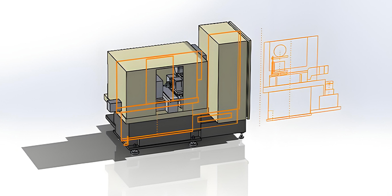
- Selection of machine tool (e.g., 5 axis cnc machine for complex parts)
- Determination of machining operations sequence
- Tool selection and cutting parameter specification
- Program coding or generation
- Program verification and simulation
- Production run and quality inspection
2. CNC Machine Coordinate Systems
Coordinate systems form the foundation of CNC machining, providing a mathematical framework for defining tool movements and part dimensions. These systems use Cartesian coordinates (X, Y, and Z axes) to specify positions in three-dimensional space, with additional axes available on more complex machines. The 5 axis cnc machine extends this concept by adding two rotational axes (typically A and B or B and C), enabling simultaneous movement in five dimensions.
The machine coordinate system (MCS) is a fixed reference frame built into the CNC machine, with its origin (X=0, Y=0, Z=0) at a predetermined point, often referred to as the machine zero or home position. This system provides a consistent reference regardless of workpiece setup. In contrast, the workpiece coordinate system (WCS) is user-defined, with its origin (usually X0, Y0, Z0) positioned at a convenient point on the workpiece, such as a corner or center.
For the 5 axis cnc machine, understanding coordinate transformations is particularly important. The additional rotational axes allow the workpiece or spindle to be oriented at various angles, effectively redefining the working plane. This capability is especially valuable for machining complex contours and undercuts that would be impossible or require multiple setups on machines with fewer axes. Proper setup of work offsets (G54-G59) is crucial to ensuring accurate part production, regardless of the machine configuration.
Modern CNC controllers offer advanced coordinate system features, including polar coordinates, cylindrical coordinates, and user-defined coordinate systems, enhancing programming flexibility. For the 5 axis cnc machine, kinematic transformations automatically calculate the required axis movements to achieve the desired tool position and orientation relative to the workpiece. Understanding these coordinate systems and their applications is fundamental to effective CNC programming, as even small errors in coordinate definition can lead to significant part inaccuracies or machine collisions.
Coordinate System Visualization
5 Axis CNC Machine Coordinate System:
- X, Y, Z: Linear axes
- A: Rotation around X-axis
- C: Rotation around Z-axis
3. Key Points in CNC Machining Process Design
CNC machining process design is a critical stage that bridges part design and manufacturing execution. It involves determining the optimal sequence of operations, tool selection, cutting parameters, and workpiece fixturing to produce high-quality parts efficiently. For complex components, the capabilities of the 5 axis cnc machine often influence process design decisions, as its multi-axis capabilities can eliminate the need for multiple setups and specialized fixtures.
One fundamental principle in process design is to establish a logical sequence of operations, typically starting with roughing to remove large volumes of material, followed by semi-finishing and finally finishing operations to achieve the required dimensional accuracy and surface finish. This approach minimizes the impact of cutting forces on part accuracy and reduces tool wear. When utilizing a 5 axis cnc machine, the process can be optimized further by maintaining consistent tool engagement and chip load throughout complex contours, improving both efficiency and tool life.
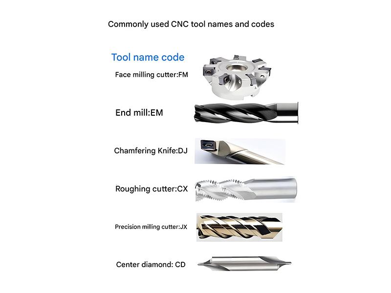
Tool selection is another critical aspect, with factors including material compatibility, cutting geometry, and tool material influencing performance. For the 5 axis cnc machine, specialized tools such as long-reach end mills or tapered tools may be required to access complex features while avoiding collisions with the workpiece or fixture. Cutting parameters—spindle speed, feed rate, and depth of cut—must be matched to the tool, material, and machine capabilities to balance productivity with tool life and part quality.
Workholding design is equally important, as secure fixturing minimizes vibration and ensures consistent positioning. The 5 axis cnc machine often allows for more efficient fixturing strategies, as its ability to access multiple part faces from a single setup reduces the number of clamping locations needed. Process designers must also consider chip management, coolant delivery, and machine capability limits when developing the machining process.
Finally, process documentation and standardization contribute to consistent results across production runs and operators. This includes detailed work instructions, tool lists, and setup sheets that specify all parameters required to execute the process. For operations involving the 5 axis cnc machine, additional documentation regarding axis limits, rotation sequences, and collision avoidance strategies is essential to ensure safe and efficient operation.
Machining Process Design Considerations
Operation Sequencing
Roughing → Semi-finishing → Finishing
Tool Selection
Material, geometry, and coating matched to workpiece
Cutting Parameters
Spindle speed, feed rate, depth of cut optimization
Workholding
Secure fixturing with minimal interference, especially critical for 5 axis cnc machine operations
Quality Control Points
In-process inspection and verification strategies
4. Codes and Program Structure
CNC programs consist of a structured sequence of commands that direct machine operations. These commands, primarily G-codes (preparatory functions) and M-codes (miscellaneous functions), define tool movements, spindle operations, coolant control, and other machine functions. While basic code structures are similar across most CNC machines, specialized equipment like the 5 axis cnc machine incorporates additional codes to control its rotational axes and coordinate transformations.
The fundamental program structure typically begins with a program name or number, followed by initialization commands that set modal values (persistent settings) such as unit mode (G21 for millimeters, G20 for inches), distance mode (G90 for absolute, G91 for incremental), and plane selection (G17 for XY plane, G18 for XZ, G19 for YZ). For the 5 axis cnc machine, additional modal commands establish rotational axis modes and coordinate system transformations.
Motion commands form the core of most CNC programs, with G00 for rapid positioning and G01, G02, G03 for linear and circular interpolations. These commands specify the target position using X, Y, Z coordinates and, for the 5 axis cnc machine, rotational axes values (A, B, or C). Feed rate (F address) and spindle speed (S address) parameters accompany these motion commands to control cutting conditions.
Miscellaneous functions (M-codes) control auxiliary machine functions, including spindle start/stop (M03, M04, M05), coolant on/off (M08, M09), and program termination (M30). Subprograms (M98, M99) allow for code reuse, particularly valuable for repetitive features. The 5 axis cnc machine may use specialized M-codes for axis locking, tool length compensation in rotated planes, and collision detection functions.
Modern CNC controllers support advanced programming features such as parametric programming, macros, and conditional logic, enabling more flexible and intelligent machining processes. These capabilities are especially powerful in the 5 axis cnc machine, where complex part geometries often require adaptive toolpaths and real-time adjustments based on measured conditions.
Regardless of complexity, well-structured CNC programs follow consistent formatting conventions, including clear commenting, logical block ordering, and appropriate use of modal commands to minimize code length. This organization enhances readability, simplifies debugging, and improves program reliability—essential qualities when programming the sophisticated movements of a 5 axis cnc machine.
Common CNC Codes Reference
| Code | Description | Application |
|---|---|---|
| G00 | Rapid positioning | Moving between operations |
| G01 | Linear interpolation | Straight cuts |
| G02/G03 | Circular interpolation | Arcs and circles |
| G90/G91 | Absolute/Incremental mode | Coordinate systems |
| G17/G18/G19 | Plane selection | Working plane definition |
| M03/M05 | Spindle start/stop | Cutting operations |
| G28 | Return to reference point | Program end/reset |
| G68/G69 | Coordinate rotation | 5 axis cnc machine operations |
Sample 5 Axis CNC Program Segment:
O0001 (5 AXIS EXAMPLE PROGRAM)
G21 G17 G40 G80 G90 (INITIALIZATION)
T1 M6 (TOOL CHANGE)
S3000 M3 (SPINDLE ON CW)
G54 G00 X50 Y30 Z10 (RAPID TO START POSITION)
G01 Z5 F200 (FEED TO WORK)
G68 X0 Y0 R45 (ROTATE COORDINATE SYSTEM 45°)
G01 X30 Y0 F100 (LINEAR CUT IN ROTATED SYSTEM)
G02 X0 Y30 I-30 J0 (ARC MOTION)
G69 (CANCEL ROTATION)
G00 Z10 (RAPID RETRACT)
M30 (PROGRAM END)
5. Programming Application Examples
CNC programming finds application across a wide range of manufacturing scenarios, from simple 2D profiling to complex 3D contouring of aerospace components. The examples below illustrate different programming approaches for various part geometries and machine configurations, including applications specifically suited to the capabilities of the 5 axis cnc machine.
In the aerospace industry, the 5 axis cnc machine is indispensable for producing turbine blades with complex twisted geometries. Programming such components requires careful consideration of tool orientation to maintain optimal cutting conditions while avoiding collisions with the workpiece. The simultaneous movement of all five axes allows the cutting tool to maintain a constant angle relative to the blade surface, resulting in superior surface finish and dimensional accuracy compared to multi-setup approaches on machines with fewer axes.
Automotive mold and die manufacturing provides another common application for advanced CNC programming. Creating the complex curved surfaces found in car body panels demands precise 3D contouring strategies. Here, the 5 axis cnc machine excels by enabling the use of shorter, more rigid cutting tools that reduce vibration and improve surface quality. Programming these surfaces typically involves CAD/CAM-generated toolpaths that optimize stepover distances and feed rates based on surface curvature.
Medical device manufacturing often requires intricate parts with tight tolerances, such as orthopedic implants. These components frequently feature complex geometries designed to match patient-specific anatomy. The 5 axis cnc machine's ability to machine complex contours from solid blanks makes it ideal for producing these customized parts. Programming considerations include specialized tooling for biocompatible materials and toolpath strategies that minimize burr formation and maintain critical surface finishes.
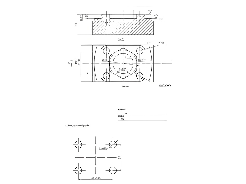
For simpler applications, such as machining a rectangular pocket in a plate, basic G-code programming suffices. The program would include rapid positioning to the start point, Z-axis plunge to the desired depth, and linear interpolation to create the pocket boundaries, possibly using a helical entry (G02/G03 with Z-axis movement) to minimize tool engagement shock. While this could be done on any CNC mill, programming efficiency is enhanced when using CAM software, even for relatively simple parts.
A particularly powerful application of the 5 axis cnc machine is in the production of impellers and blisks (bladed disks) for turbomachinery. These components feature complex curved surfaces and overlapping blades that would be impossible to machine completely on machines with fewer axes. Programming these parts requires advanced CAM software capable of generating collision-free toolpaths that maintain proper tool orientation throughout the machining process. The resulting programs can contain thousands of blocks of code, with precise control over all five axes to achieve the required geometry.

Aerospace Component Machining
The 5 axis cnc machine enables precise machining of complex aerospace parts with contoured surfaces, reducing setup time and improving accuracy compared to traditional methods.
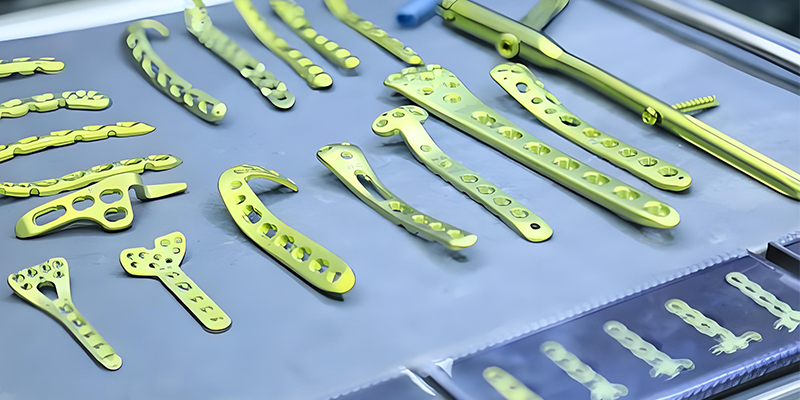
Medical Implant Manufacturing
Custom medical implants require precise programming to achieve patient-specific geometries, a task ideally suited to the 5 axis cnc machine's capabilities.
Programming Application Comparison
6. Automatic Programming
Automatic programming, often referred to as computer-aided manufacturing (CAM), revolutionizes CNC programming by leveraging software to generate machine code from 3D CAD models. This approach eliminates the need for manual G-code writing, significantly reducing programming time and minimizing errors, especially for complex parts that would be impractical to program manually. For the 5 axis cnc machine, automatic programming is virtually indispensable due to the complex coordinate transformations and tool orientation calculations required.
The automatic programming workflow typically begins with importing a 3D CAD model into the CAM software. The programmer then defines the workpiece material, selects appropriate cutting tools from a digital library, and specifies machining operations (roughing, finishing, drilling, etc.). For 5 axis cnc machine programming, additional steps include defining the machine's kinematic configuration and setting up axis limits to prevent collisions.
CAM software uses sophisticated algorithms to generate optimal toolpaths based on the selected parameters. For the 5 axis cnc machine, these algorithms must account for simultaneous movement of all axes, maintaining proper tool orientation relative to the part surface while avoiding collisions with the workpiece, fixture, and machine components. Advanced CAM systems offer adaptive toolpath strategies that optimize cutting conditions based on material removal rates, significantly reducing cycle times.
Verification and simulation are critical stages in automatic programming. CAM software provides 3D visualization of the machining process, allowing programmers to check for potential collisions, verify toolpaths, and simulate material removal. For the 5 axis cnc machine, this simulation is particularly important due to the complex multi-axis movements that can create unexpected interference issues. Some advanced systems even incorporate machine-specific kinematic models to ensure the simulated behavior matches the actual machine performance.
Post-processing represents the final step in automatic programming, converting the CAM-generated toolpaths into machine-specific G-code that the CNC controller can execute. Post-processors are customized for specific machine makes and models, accounting for unique features and capabilities. For the 5 axis cnc machine, post-processors must handle the complex coordinate transformations and axis movements specific to that machine's configuration (e.g., table-table, head-table, or head-head design).
Modern automatic programming systems offer integration with other manufacturing software, including CAD systems for seamless design-to-manufacturing workflows, and manufacturing execution systems (MES) for production planning and tracking. This integration enables a digital thread贯穿整个制造过程, from design concept to finished part.
The adoption of automatic programming has been particularly transformative for 5 axis cnc machine applications, unlocking their full potential for producing complex parts while maintaining programming efficiency. As artificial intelligence and machine learning continue to advance, automatic programming systems are becoming increasingly intelligent, with capabilities such as feature recognition, process optimization, and even predictive tool life management, further enhancing the productivity and capabilities of CNC machining operations.
Automatic Programming Workflow
CAD Model Import
3D design data imported into CAM software
Part Setup Definition
Workpiece orientation, fixtures, and stock material
Toolpath Generation
Automatic calculation of cutting paths, optimized for 5 axis cnc machine capabilities
Simulation & Verification
Collision checking and machining process visualization
Post-Processing
Conversion to machine-specific G-code for the 5 axis cnc machine
Machine Execution
Transfer to CNC controller and production run
Key Benefits of Automatic Programming for 5 Axis CNC Machine:
- Eliminates manual calculation of complex multi-axis movements
- Reduces programming time by up to 90% compared to manual methods
- Enables collision detection in complex machining scenarios
- Optimizes toolpaths for improved surface finish and tool life
- Facilitates programming of complex geometries impossible to code manually