Feed Servo Drive System Technology
Advanced solutions for precision motion control in industrial automation, including the critical role in cnc lathe machine operations and beyond.
Precision motion control systems powering modern manufacturing excellence
1 Feed Servo Drive System Overview
A feed servo drive system is a critical component in modern industrial automation, responsible for precisely controlling the position, velocity, and acceleration of machine tool axes—key for small cnc machine. These systems convert electrical signals into mechanical motion with exceptional accuracy, making them indispensable in applications ranging from simple positioning tasks to complex multi-axis machining operations.
In the context of a cnc lathe machine, the feed servo drive system regulates the movement of the cutting tool relative to the workpiece, ensuring precise dimensional control and surface finish. The performance of these systems directly impacts the quality of manufactured components, production efficiency, and overall machine productivity.
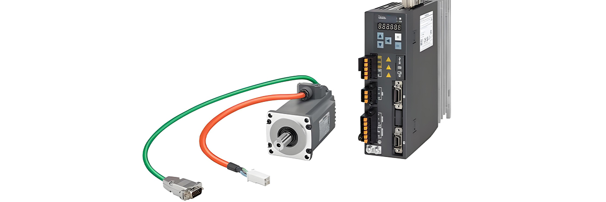
A basic feed servo drive system consists of several key components working in harmony: a servo motor that generates the mechanical motion, a drive amplifier that controls the motor, a position feedback device that monitors actual position, and a controller that processes commands and closes the control loop.
Modern servo drive systems utilize sophisticated control algorithms to achieve high dynamic response and positioning accuracy. These systems can compensate for mechanical imperfections, external disturbances, and varying load conditions, maintaining optimal performance across a wide range of operating parameters.
The integration of digital signal processing (DSP) technology has revolutionized feed servo systems, enabling real-time adjustment of control parameters and advanced diagnostic capabilities. This digital transformation has significantly improved system reliability and reduced maintenance requirements, particularly in high-duty-cycle applications like the cnc lathe machine and cnc machining bronze.
Feed servo drive systems are classified based on several criteria, including the type of motor used (DC, AC induction, AC synchronous), the control method (open-loop, closed-loop), and the power rating. Each classification offers distinct advantages in specific applications, with AC synchronous systems currently dominating high-performance applications due to their superior power density and efficiency.
As manufacturing requirements continue to evolve toward higher precision and productivity, feed servo drive systems are being pushed to deliver faster response times, higher torque densities, and improved energy efficiency. These advancements are critical for meeting the demands of modern manufacturing processes, including those found in state-of-the-art cnc lathe machine technology.
Servo Drive System Block Diagram
Key Performance Metrics
2 Position Detection Devices
Position detection devices, critical for laser cnc machine, are fundamental components of closed-loop feed servo drive systems, providing accurate feedback on the actual position of the motor shaft or load. This feedback is essential for the controller to compare against the desired position and generate appropriate correction signals, ensuring precise motion control.
In a cnc lathe machine, the accuracy of position detection directly influences the dimensional precision of machined parts. Even minor position errors can lead to significant quality issues, making the selection and implementation of appropriate detection devices critical for manufacturing success.
Encoders represent the most common type of position detection device used in servo systems. These devices convert mechanical motion into electrical signals that can be interpreted by the controller. Two primary encoder types are employed: incremental encoders and absolute encoders, each offering distinct advantages in specific applications.
Incremental encoders generate pulses as the shaft rotates, with the controller counting these pulses to determine position relative to a starting point. They are cost-effective and provide high resolution, making them suitable for many applications including basic cnc lathe machine operations. However, they require a reference point to establish absolute position after power-up.
Absolute encoders, in contrast, provide a unique code for each position, enabling immediate determination of absolute position without reference to a home position. This feature is particularly valuable in applications where power interruptions may occur, as it eliminates the need for re-homing cycles. Absolute encoders are available in single-turn and multi-turn configurations, with the latter capable of tracking position across multiple revolutions.
Resolvers are another type of position detection device, offering robust performance in harsh environments with high vibration, temperature extremes, or electromagnetic interference. These electromechanical devices use transformer principles to generate analog signals proportional to shaft position, which are then converted to digital form for processing by the controller.
Linear scales represent a specialized form of position detection used for direct measurement of linear motion, bypassing potential errors introduced by mechanical transmission components. These devices are particularly valuable in high-precision applications, providing feedback directly from the moving axis rather than the motor shaft. In advanced cnc lathe machine systems, linear scales can significantly improve positioning accuracy by eliminating backlash and compliance effects in the drive train.
The selection of an appropriate position detection device depends on several factors, including required accuracy, resolution, operating environment, cost constraints, and system response requirements. As manufacturing precision requirements continue to tighten, the trend is toward higher resolution devices with faster data transmission rates to support the advanced control algorithms used in modern servo systems.
Encoder Technologies Comparison
| Technology | Resolution | Accuracy | Environmental Resistance | Cost |
|---|---|---|---|---|
| Incremental Encoder | High (up to 100,000 PPR) | Good | Moderate | Low |
| Absolute Encoder | High | Excellent | Moderate | High |
| Resolver | Medium-High | Good | Excellent | Medium |
| Linear Scale | Very High | Excellent | Moderate-Poor | Very High |
Encoder Working Principle
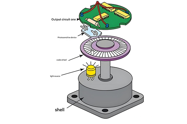
Optical encoder operation: Light passes through patterned disk to photodetectors, generating position signals
3 AC Permanent Magnet Synchronous Feed Servo Motor and Drive System
AC permanent magnet synchronous servo motors (PMSMs) have emerged as the dominant technology in high-performance feed servo drive systems, offering superior power density, efficiency, and dynamic response compared to alternative motor technologies. These motors combine the advantages of AC operation with the high torque characteristics of permanent magnet excitation, making them ideal for precision motion control applications.Optical Transceiver.
In the context of a cnc lathe machine, PMSMs deliver the precise torque and speed control required for accurate machining operations in desktop cnc milling machine too. Their ability to maintain constant torque across a wide speed range ensures consistent performance during both heavy cutting operations and fine finishing passes.
The construction of a PMSM typically includes a stator with three-phase windings similar to an induction motor, and a rotor containing high-strength permanent magnets. These magnets generate a constant magnetic field, eliminating the need for rotor windings and slip rings, which simplifies construction and improves reliability.
The drive system for a PMSM consists of power electronics that convert DC bus voltage to three-phase AC with variable frequency and amplitude. This conversion is managed by sophisticated control algorithms that regulate torque and speed by precisely synchronizing the stator current with the rotor position.
Vector control (field-oriented control) represents the state-of-the-art in PMSM drive technology, enabling independent control of torque and flux components. This technique transforms the three-phase current into a rotating reference frame, allowing control strategies similar to those used in DC motor drives. The result is exceptional dynamic performance with fast response to command changes, a critical requirement in cnc lathe machine applications where rapid tool movements and precise positioning are essential.
PMSM drive systems require accurate rotor position information for proper operation, typically provided by high-resolution encoders or resolvers. This position feedback enables the drive to maintain precise synchronization between the stator magnetic field and the rotor position, maximizing torque production and efficiency.
One of the key advantages of PMSM technology is its high power density, which allows for compact motor designs with high torque output. This is particularly beneficial in space-constrained applications like cnc lathe machine tool turrets, where multiple axes must be integrated into a limited space. Additionally, PMSMs exhibit exhibit lower rotor inertia compared to induction motors, enabling faster acceleration and deceleration.
Efficiency is another significant advantage of PMSM drive systems, especially at partial loads. Unlike induction motors, which suffer from rotor copper losses, PMSMs eliminate these losses due to their permanent magnet excitation. This efficiency improvement translates to reduced energy consumption and lower operating costs, particularly in high-duty-cycle manufacturing environments.
PMSM Cross-Section and Drive Circuit
Torque-Speed Characteristics
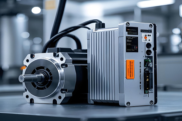
4 AC Permanent Magnet Synchronous Feed Servo Drive System
The AC permanent magnet synchronous feed servo drive system represents the integration of PMSM technology with advanced drive electronics and control algorithms to deliver precise motion control. This complete system solution provides the foundation for high-performance automation in modern manufacturing environments, offering unparalleled accuracy and responsiveness.
At the heart of these drive systems, used in five axis cnc machine and cnc lathe machine, lies sophisticated digital signal processing that enables real-time implementation of complex control strategies. These processors manage all aspects of system operation, from interpreting position commands to regulating power device switching, ensuring optimal performance across the entire operating range.
The power stage of the servo drive converts DC input power (typically from a rectified AC source) into three-phase AC power with variable frequency and amplitude to drive the PMSM. This conversion is accomplished using insulated-gate bipolar transistors (IGBTs) or metal-oxide-semiconductor field-effect transistors (MOSFETs) that switch at high frequencies, enabling precise control of motor current and voltage.
Current control represents a critical function within the servo drive, with sophisticated algorithms regulating the current in each motor phase to achieve the desired torque output. Advanced drives employ predictive current control techniques that anticipate switching events, minimizing current ripple and improving dynamic response. This level of precision is particularly important in cnc lathe machine applications where smooth motion and consistent torque are essential for achieving superior surface finishes.
Position and velocity control loops work in tandem to ensure the motor follows the commanded motion profile accurately. The position loop compares the commanded position with feedback from the position detection device, generating a velocity command to minimize any position error. The velocity loop then regulates motor speed to match this command, adjusting torque output as necessary to overcome disturbances and maintain performance.
Modern servo drives incorporate advanced features such as auto-tuning, which automatically configures control parameters based on the mechanical system characteristics. This simplifies system commissioning and ensures optimal performance without requiring extensive expertise. Adaptive control algorithms further enhance performance by continuously adjusting parameters to compensate for changes in load conditions or environmental factors.
Communication capabilities are another key feature of contemporary servo drive systems, enabling seamless integration into industrial networks. Standardized protocols such as EtherCAT, PROFINET, and SERCOS III facilitate high-speed data exchange between drives and higher-level controllers, enabling coordinated motion across multiple axes in complex cnc lathe machine systems.
Safety functions have become increasingly important in servo drive design, with features such as safe torque off (STO) preventing unexpected motion during maintenance or in emergency situations. These safety mechanisms comply with international standards, ensuring safe operation while minimizing downtime.
Diagnostic and monitoring capabilities round out the feature set of modern servo drives, providing valuable insights into system performance and health. Advanced drives offer real-time data on operating parameters, fault history, and performance metrics, enabling predictive maintenance and minimizing unplanned downtime in critical manufacturing operations.
Servo Drive Control Loops
Servo Drive Performance in CNC Applications
High-performance servo drives enable precise contouring and surface finishes in modern cnc lathe machine operations
5 AC Feed Servo Drive Technology Development Trends
AC feed servo drive technology continues to evolve rapidly, driven by advancements in power electronics, microprocessor performance, and control algorithms. These developments are increasingly focused on meeting the demanding requirements of modern manufacturing—such as best cnc machines—including higher precision, faster response, improved energy efficiency, and enhanced connectivity.
One significant trend is the ongoing miniaturization of servo drive components, enabled by higher power density power devices and more efficient thermal management techniques. This reduction in size allows for more compact machine designs and facilitates the integration of drive electronics directly into motor housings, creating integrated servo motors that simplify machine design and reduce wiring complexity. This is particularly beneficial in space-constrained applications like cnc lathe machine tool turrets and gantries.
The integration of artificial intelligence and machine learning techniques represents another important development direction. These advanced algorithms enable servo drives to adapt autonomously to changing operating conditions, optimize performance parameters in real-time, and even predict and prevent potential failures. In cnc lathe machine applications, AI-enhanced servo drives can recognize different machining conditions and automatically adjust parameters to optimize surface finish, tool life, and cycle time.
Increased energy efficiency is a persistent trend in servo drive development, driven by both environmental concerns and economic factors. Modern drives incorporate features such as regenerative braking, which captures energy during deceleration and feeds it back into the electrical grid, reducing overall energy consumption. Additionally, improved power device technology and more efficient control algorithms minimize power losses within the drive itself.
Communication capabilities are becoming increasingly sophisticated, with servo drives incorporating higher-speed industrial Ethernet protocols to enable tighter integration into smart manufacturing systems. These advanced communication capabilities facilitate real-time data exchange, enabling more precise coordination between multiple axes and providing valuable performance data for overall equipment effectiveness (OEE) monitoring and process optimization in cnc lathe machine operations.
Another notable trend is the development of more robust servo drives capable of operating in harsh environments. This includes improved protection against dust, moisture, and vibration, as well as enhanced resistance to electromagnetic interference. These ruggedized drives expand the range of applications where servo technology can be employed, including demanding industrial environments previously unsuitable for precision motion control systems.
The emergence of digital twin technology is also influencing servo drive development, with manufacturers creating virtual replicas of drive systems to enable offline simulation, optimization, and troubleshooting. This technology allows for more efficient system commissioning, as parameters can be optimized in a virtual environment before being downloaded to physical drives. In cnc lathe machine applications, digital twins enable complete virtual testing of machining processes, reducing setup time and minimizing material waste.
Finally, there is a growing focus on simplifying servo drive setup and operation, with intuitive user interfaces and automated configuration tools reducing the expertise required for proper system implementation. This trend is making advanced servo technology accessible to a broader range of manufacturers, enabling smaller operations to benefit from the same precision and performance previously available only to large manufacturers with specialized expertise.
Technology Development Roadmap
2020
High-resolution feedback integration, basic AI parameter optimization
2022
EtherCAT synchronization, energy recovery systems, improved thermal management
2024
Integrated motor-drive designs, advanced predictive maintenance, enhanced AI control
2026 (Predicted)
Autonomous adaptation, digital twin integration, energy harvesting capabilities
2030 (Predicted)
Quantum computing optimized controls, self-healing systems, fully integrated smart factory ecosystems
Key Performance Improvements
Future Servo Drive in Smart Manufacturing
Next-generation servo drives will be integral components of fully connected smart manufacturing systems, including advanced cnc lathe machine environments
6 Performance Analysis of Feed Servo Drive Systems
Performance analysis of feed servo drive systems is essential for understanding their capabilities, optimizing their operation, and selecting appropriate systems—considering cnc machine cost—for specific applications. This analysis encompasses a range of key metrics that quantify the system's ability to achieve precise motion control under various operating conditions.
Positioning accuracy represents one of the most critical performance metrics, measuring the difference between the commanded position and the actual achieved position. This parameter is particularly important in cnc lathe machine applications, where it directly impacts the dimensional precision of machined components. Accuracy is influenced by factors such as feedback device resolution, control algorithm performance, and mechanical system characteristics.
Repeatability, closely related to accuracy, measures the system's ability to return to the same position repeatedly. High repeatability ensures consistent performance over multiple machining cycles, which is essential for maintaining part consistency in high-volume production. Even if a system exhibits some positional error, good repeatability allows for compensation strategies to achieve acceptable part quality.
Dynamic response characteristics quantify how quickly the servo system can accelerate, decelerate, and change direction in response to command signals. This is typically evaluated using step response tests, where the system's reaction to an abrupt position or velocity command is measured. Key parameters include rise time, settling time, and overshoot, all of which impact the productivity and accuracy of cnc lathe machine operations.
Velocity range and torque characteristics define the operational envelope of the servo drive system. The system must provide sufficient torque across the entire speed range to accelerate the load and overcome friction and cutting forces. In cnc lathe machine applications, this includes maintaining adequate torque at low speeds for precise positioning and providing sufficient peak torque for rapid accelerations during tool changes and positioning moves.
Tracking accuracy evaluates the system's ability to follow complex motion profiles, such as circular interpolation paths commonly used in contouring operations. This is often assessed using circular tests, where the system's ability to maintain a circular path at various feed rates is measured. Poor tracking accuracy can result in contour errors that degrade part quality, making this metric particularly important for precision machining applications.
Disturbance rejection measures the system's ability to maintain performance in the presence of external forces, such as cutting forces in a cnc lathe machine. A servo system with good disturbance rejection will minimize position errors when subjected to varying loads, ensuring consistent part quality even during heavy cutting operations.
Thermal performance analysis evaluates how the servo drive system behaves under sustained operation, ensuring that temperature rises do not degrade performance or cause premature component failure. This is particularly important in high-duty-cycle applications where the drive may operate near its power limits for extended periods.
Energy efficiency analysis quantifies the system's energy consumption under various operating conditions, identifying opportunities for energy savings. This includes evaluating both the drive electronics efficiency and the motor efficiency across the operating range, as well as considering regenerative capabilities during deceleration.Electronic shelf labels.
Finally, reliability and durability analysis assesses the system's performance over extended periods and under varying environmental conditions. This includes evaluating mean time between failures (MTBF), resistance to vibration and shock, and performance under extreme temperature and humidity conditions. For manufacturing applications, high reliability is essential for minimizing downtime and maintaining production schedules.Related Hydraulic Spare Parts.
Comprehensive performance analysis involves both simulation and physical testing, with advanced test rigs capable of evaluating servo systems under realistic load conditions. This analysis provides valuable insights for system optimization, helping manufacturers select the appropriate servo drive system for their specific cnc lathe machine applications and configure it for optimal performance. Related Lithium Battery Manufacturing.
Performance Metrics Evaluation
Step Response Characteristics
Performance Comparison Table
| Performance Metric | Importance in CNC Lathe | Measurement Method | Typical Specification |
|---|---|---|---|
| Positioning Accuracy | Critical | Laser interferometer | ±0.001 mm to ±0.01 mm |
| Repeatability | Critical | Multiple position tests | ±0.0005 mm to ±0.005 mm |
| Maximum Velocity | High | Velocity profile testing | 50-600 m/min |
| Acceleration | High | Ramp response testing | 0.5-10 g |
| Contour Accuracy | Critical | Circular test | 0.002-0.02 mm at 3000 mm/min |
| Disturbance Rejection | High | Load variation testing | <5% position error under load |