CNC Programming Fundamentals
A comprehensive guide to numerical control programming for precision manufacturing and cnc machining services
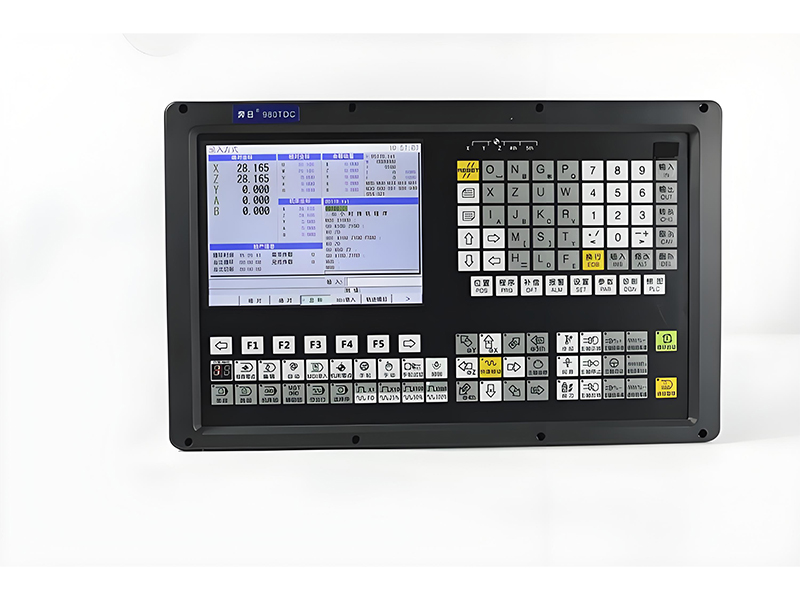
CNC programming is the process of creating instructions for a computer numerical control (CNC) machine to produce parts through cnc machining services. These instructions, called G-code, direct the machine's movements, speeds, and operations with extreme precision.
Modern manufacturing’s cnc machining jobs—which demand complex parts with consistent accuracy—rely heavily on CNC programming, a capability impossible to replicate with manual machining. The programming process translates engineering drawings into a language that CNC machines can understand and execute, directly enabling the completion of these precision-focused jobs.
Effective CNC programming requires a combination of engineering knowledge, understanding of machining processes, and familiarity with specific machine capabilities. Professionals in cnc machining services must master both the technical aspects of programming and the practical considerations of material properties and tooling.
The evolution of CNC programming has paralleled advances in computer technology, moving from punched tape systems to sophisticated CAD/CAM software that integrates with the latest cnc machine tools and cnc machining services. This evolution has significantly reduced programming time while increasing the complexity of parts that can be produced.
Key benefits of proper CNC programming include:
- Consistent part production with minimal variation
- Reduced setup and production times
- Ability to produce complex geometries
- Improved material utilization and reduced waste
- Enhanced safety through precise control of machine movements
CNC Programming Workflow
- Part design and engineering drawing
- Determination of machining processes
- Tool selection and setup planning
- Program writing or generation
- Simulation and verification
- Machine setup and production
- Inspection and program refinement
Importance in Modern Manufacturing
As manufacturing tolerances continue to shrink and part complexity increases, the role of precise CNC programming becomes even more critical. Leading
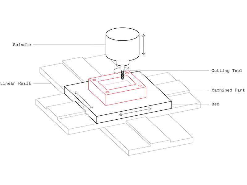
Understanding coordinate systems is fundamental to CNC programming—especially for cnc milling machine programming, where clear coordinate definitions directly determine the machine’s ability to mill complex shapes with tight tolerances— as they define the position and movement of the cutting tool relative to the workpiece. Properly establishing and using coordinate systems ensures accuracy and repeatability in cnc machining services, a requirement that starts with calibrating coordinate parameters for CNC milling machines before production. The machine coordinate system is a fixed reference system built into the CNC machine, with its origin (X=0, Y=0, Z=0) at a permanent position, typically the machine's home position. This system remains constant regardless of workpiece changes and serves as the ultimate reference for all machine movements in professional cnc machining services. The workpiece coordinate system is programmable and is set relative to the workpiece. Its origin (usually X0, Y0) is typically established at a convenient point on the part, such as a corner or center. G-code commands like G54-G59 are used to set multiple workpiece coordinate systems, essential for complex setups in cnc machining services. A temporary coordinate system that can be established within a program using G92 or G52 commands, allowing for easier programming of repetitive features. This system is particularly useful for subprograms and repeating patterns common in specialized cnc machining services. CNC machines use a standardized axis naming convention to ensure consistency across different machine types and cnc machining services: 3D Cartesian coordinate system showing X, Y, and Z axes with positive direction arrows Work offsets are critical for accurate part production in cnc machining services. They establish the relationship between the machine's coordinate system and the workpiece's coordinate system. Many modern CNC machines used in advanced cnc machining services feature: Effective process design is the foundation of successful CNC machining—serving as the core prerequisite for precision cnc machining, a high-value segment of CNC services that hinges on process design to achieve tight tolerances (often ±0.001mm) and consistent part quality. It involves planning every aspect of the manufacturing process (from material selection to post-processing) to ensure efficiency, accuracy, and cost-effectiveness in cnc machining services, with precision cnc machining acting as the key benchmark for evaluating process design effectiveness.Optical Transceiver. Before any machining begins, thorough part analysis is essential. This step determines the feasibility and optimal approach for cnc machining services. Engineers must interpret technical drawings, noting dimensions, tolerances, surface finishes, and material specifications that impact the machining process. Critical dimensions and their tolerances determine machine selection, tooling requirements, and inspection methods in precision cnc machining services. Material properties (hardness, machinability, thermal characteristics) influence tool selection, cutting parameters, and overall process design. The order of machining operations significantly impacts part quality, production time, and tool life in cnc machining services. Optimal sequencing follows these principles: Choosing appropriate cutting tools based on material, operation type, and surface finish requirements is crucial for efficient cnc machining services—even for a small cnc machine. Factors include tool material, geometry, coating, and holder design. Optimal speed, feed rate, and depth of cut balance material removal rate with tool life. These parameters vary by material, tooling, and machine capability in professional cnc machining services. Proper workholding ensures part stability during machining, minimizing deflection and maximizing accuracy. Fixturing should allow easy loading/unloading while providing sufficient clamping force. Continuous improvement of machining processes is essential for competitive cnc machining services. Key optimization strategies include: Minimizing non-cutting time through optimized tool paths and rapid movements Optimizing cutting parameters to extend tool life and reduce changeover time Nesting parts and optimizing blank sizes to minimize waste Combining operations on multi-axis machines to reduce setups CNC programs follow a specific structure and use standardized commands to communicate with the machine controller— a key part of a CNC machine, as outlined in the cnc machine definition (which describes CNC machines as computer-controlled tools that execute machining tasks via programmed commands). Understanding this structure is essential for writing effective programs for cnc machining services, as the programs must align with the operational principles of CNC machines defined in this core concept. A well-organized CNC program enhances readability, simplifies troubleshooting, and ensures consistent execution in cnc machining services. The typical structure includes: Contains program number (Oxxxx), part name, revision, and date Initializes machine to safe state (G21, G17, G40, G49, G50, etc.) Specifies work offsets (G54-G59), spindle speeds, and feed rates Contains sequence of machining operations and tool changes Reusable code blocks for repetitive features (M98/M99) Final commands (M30) to reset machine and end program ; Example CNC Milling Program O0001 ; Program number ; Part Name: Mounting Bracket ; Material: Aluminum 6061 N10 G21 G17 G40 G49 G50 G90 ; Safety block N20 G54 ; Work offset N30 T1 M6 ; Tool change to 1 (50mm face mill) N40 S2500 M3 ; Spindle on CW at 2500 RPM N50 G0 X0 Y0 Z50 ; Rapid to safe position N60 G0 Z5 ; Rapid to 5mm above workpiece N70 G1 Z-2 F100 ; Feed to cutting depth N80 G1 X50 Y0 F300 ; Face mill X direction N90 G1 Y50 ; Face mill Y direction N100 G1 X0 ; Face mill X direction N110 G1 Y0 ; Face mill Y direction N120 G0 Z50 ; Retract to safe height N130 T2 M6 ; Tool change to 2 (10mm drill) N140 S3000 M3 ; Spindle on CW at 3000 RPM N150 G0 X25 Y25 Z50 ; Rapid to hole position N160 G81 R5 Z-15 F200 ; Drill cycle N170 G80 ; Cancel drill cycle N180 G0 Z50 ; Retract N190 M30 ; Program end and reset Example CNC milling program showing standard structure used in cnc machining services G-codes (preparatory codes) establish modal conditions or initiate specific actions. They form the core of programming language in cnc machining services. M-codes (miscellaneous codes) control machine functions and auxiliary equipment, playing a vital role in automated cnc machining services. Practical examples—often embodied as cnc machine projects (e.g., custom metal part milling, batch production of plastic components, or precision drilling of automotive parts)—help illustrate how CNC programming concepts are applied in real-world manufacturing scenarios. These cnc machine projects, in turn, demonstrate typical applications in cnc machining services, bridging programming theory and service delivery. Face milling is a common operation to create flat surfaces on workpieces. This example demonstrates a basic face milling program used in cnc machining services to create a flat surface on a rectangular workpiece. O0002 ; Face milling program N10 G21 G17 G40 G49 G50 G90 ; Safety block N20 G54 ; Work offset N30 T1 M6 ; Load face mill N40 S3000 M3 ; Spindle on CW N50 G0 X-10 Y-10 Z50 ; Rapid to start position N60 G0 Z5 ; Rapid to 5mm above workpiece N70 G1 Z-2 F100 ; Feed to cutting depth N80 G1 X110 F400 ; First pass - full width N90 G1 Y0 ; Step over N100 G1 X-10 ; Second pass N110 G1 Y10 ; Step over N120 G1 X110 ; Third pass N130 G1 Y20 ; Step over N140 G1 X-10 ; Fourth pass N150 G0 Z50 ; Retract to safe height N160 M30 ; Program end This example demonstrates using a fixed cycle (G81) to drill multiple holes in a pattern, a common requirement in cnc machining services. Fixed cycles reduce programming time and improve consistency. O0003 ; Hole drilling program N10 G21 G17 G40 G49 G50 G90 ; Safety block N20 G54 ; Work offset N30 T2 M6 ; Load drill N40 S1500 M3 ; Spindle on CW N50 M8 ; Coolant on N60 G0 X20 Y20 Z50 ; Rapid to first hole N70 G81 R5 Z-22 F100 ; Drill cycle setup N80 X50 Y20 ; Second hole position N90 X80 Y20 ; Third hole position N100 X50 Y50 ; Fourth hole position N110 X50 Y80 ; Fifth hole position N120 G80 ; Cancel drill cycle N130 G0 Z50 ; Retract to safe height N140 M9 ; Coolant off N150 M30 ; Program end Contour milling creates complex shapes using linear and circular interpolation. This example shows how to machine a rectangular part with rounded corners, demonstrating techniques essential for cnc machining services producing complex components. O0004 ; Contour milling program N10 G21 G17 G40 G49 G50 G90 ; Safety block N20 G54 ; Work offset N30 T3 M6 ; Load end mill N40 S2000 M3 ; Spindle on CW N50 M8 ; Coolant on N60 G0 X0 Y0 Z50 ; Rapid to start position N70 G0 Z5 ; Rapid to 5mm above N80 G1 Z-5 F100 ; Feed to depth N90 G41 D3 X10 Y0 F250 ; Activate radius comp N100 G1 X70 ; Linear cut N110 G2 X80 Y10 I0 J10 ; CW arc N120 G1 Y50 ; Linear cut N130 G2 X70 Y60 I-10 J0 ; CW arc N140 G1 X10 ; Linear cut N150 G2 X0 Y50 I0 J-10 ; CW arc N160 G1 Y10 ; Linear cut N170 G2 X10 Y0 I10 J0 ; CW arc - close contour N180 G40 G1 X0 Y0 ; Cancel radius comp N190 G0 Z50 ; Retract N200 M9 ; Coolant off N210 M30 ; Program end These examples represent fundamental operations that form the building blocks of more complex parts. In professional cnc machining services, these basic operations are combined and extended to produce intricate components with multiple features. The key is to understand how to sequence operations, select appropriate tools, and apply the correct cutting parameters for each material and feature type. Automatic programming, or computer-aided programming, is the backbone of cnc machining online (an online CNC service where clients remotely submit 3D models and receive generated CNC code or finished parts)—as it uses software to generate CNC code from 3D models, significantly increasing productivity in modern cnc machining services. This approach not only reduces manual programming errors and enables the production of complex geometries that would be impractical to program manually but also supports the seamless workflow of cnc machining online: clients upload models to online platforms, automatic programming tools generate code instantly, and manufacturers execute processing without offline communication barriers. The integration of Computer-Aided Design (CAD) and Computer-Aided Manufacturing (CAM) has revolutionized cnc machining services, creating a seamless digital thread from design to production. The process begins with creating a 3D model of the part using CAD software. This digital representation contains all geometric and dimensional information needed for manufacturing. The CAD model is prepared for manufacturing by adding necessary information such as material, tolerances, and surface finish requirements specific to cnc machining services. The prepared CAD model is imported into CAM software where machining operations are defined, including toolpaths, cutting parameters, and machine selection. Toolpaths are simulated to check for collisions, verify material removal, and ensure the part meets design specifications before actual machining. Once verified, the CAM software post-processes the toolpaths into machine-specific G-code that can be directly loaded into CNC machines. Includes high-speed machining, trochoidal milling, and rest material machining to optimize cutting performance for various materials in cnc machining services. Provides realistic 3D visualization of the machining process, detecting collisions between tools, workpieces, fixtures, and machine components. Converts toolpaths into machine-specific G-code, accounting for unique machine capabilities, kinematics, and control systems used in cnc machining services. Automatically identifies manufacturing features (holes, slots, pockets) in CAD models, reducing programming time and ensuring consistent feature processing. Maintains link between CAM data and CAD model, automatically updating toolpaths when design changes occur, critical for agile cnc machining services. Analyzes and optimizes toolpaths to minimize cycle time, reduce tool wear, and improve surface finish through intelligent feed rate adjustments. The evolution of automatic programming continues to accelerate, driven by advancements in artificial intelligence, machine learning, and connectivity. These trends are transforming cnc machining services: Machine learning algorithms that automatically select optimal cutting strategies based on material, part geometry, and machine capabilities Virtual replicas of machines and processes that enable complete simulation before physical production begins Web-accessible programming tools that enable collaboration, remote programming, and real-time process monitoring,Related Hydraulic Spare Parts. Closed-loop systems that adjust toolpaths in real-time based on sensor data from the machine, optimizing for variations Electronic shelf labels These advancements are making cnc machining services more efficient, flexible, and accessible, while enabling the production of increasingly complex components with higher precision. Related Lithium Battery Manufacturing.Machine Coordinate System (MCS)
Workpiece Coordinate System (WCS)
Local/Program Coordinate System
Axis Designations
Setting Work Offsets
Manual Offset Setting Process:
Automatic Offset Setting:
Part Analysis and Preparation
Drawing Interpretation
Tolerance Analysis
Material Considerations
Key Questions in Process Design:
Machining Sequence Optimization
Operation Order
Typical Operations
Rationale
1. First Operations
Facing,flat milling, Reference surface machining
Establishes reference surfaces for subsequent operations
2. Roughing
Heavy material removal, Rough milling, Rough turning
Removes bulk material quickly, leaves minimal stock for finishing
3. Semi-finishing
Contour machining, slotting, Semi-finishing milling
Brings part close to final dimensions, prepares for finishing
4. Heat Treatment
Hardening, annealing, stress relieving
Performed before final finishing when required
5. Finishing
Precision milling, turning, boring
Achieves final dimensions and surface finishes
6. Secondary Operations
Drilling, tapping, threading
Adds features that would be damaged by earlier operations
Tool Selection
Cutting Parameters
Fixturing Design
Process Optimization for cnc machining services
Cycle Time Reduction
Tool Life Maximization
Material Utilization
Process Integration
Program Structure
Program Header
Safety Block
Setup Information
Main Program
Subprograms
Program End
Common G-Codes
Motion Codes
Modal Codes
Miscellaneous Codes
Common M-Codes
Code
Function
Application
M00
Program stop
Temporary halt requiring operator resume
M01
Optional stop
Halt only if optional stop button activated
M03
Spindle start clockwise
Initiates spindle rotation CW
M04
Spindle start counter-clockwise
Initiates spindle rotation CCW
M05
Spindle stop
Stops spindle rotation
M06
Tool change
Automatic tool changer activation
M08
Coolant on
Activates flood coolant system
M09
Coolant off
Deactivates all coolant systems
M30
Program end and reset
Ends program and returns to start
Important Programming Considerations
Example 1: Face Milling
Operation Parameters:
Example 2: Drilling Multiple Holes
Operation Parameters:

Example 3: Contour Milling
Operation Parameters:
Application in cnc machining services
CAD/CAM Workflow
1. CAD Model Creation
2. Model Preparation
3. CAM Programming
4. Simulation & Verification
5. G-Code Generation
Benefits of Automatic Programming
Key Features of Modern CAM Software
Advanced Toolpath Strategies
3D Simulation
Machine Specific Post-Processors
Feature Recognition
Associativity
Process Optimization
Future Trends in Automatic Programming
AI-Driven Toolpath Generation
Digital Twins
Cloud-Based CAM
Adaptive Machining